Fibronexa Fibronexa

Why Choose a Multimode Transceiver for Global Networks?

Time:2026-10-05 Author:Liam
0%

Global networks rarely fail because one link lacks speed. They fail when interfaces, distances, and operating conditions do not match. A multimode transceiver can simplify this challenge by supporting short-reach connections across data centers, enterprise campuses, and regional facilities. In a typical rack, it may connect switches through OM3 or OM4 fiber, reducing unnecessary conversion equipment and keeping patching easier to inspect. That practical benefit matters during maintenance, when a mislabeled cable can delay a service window.

Network engineers usually assess more than advertised bandwidth. They check wavelength, connector type, reach, fiber grade, power consumption, temperature range, and switch compatibility. Vendor documentation, interoperability testing, and optical monitoring provide stronger evidence than a product label alone. Standards-based selection also improves confidence when equipment comes from different suppliers. A reliable deployment records transceiver models, serial numbers, test results, and replacement procedures. Small details matter.

Still, multimode is not a universal answer. Longer metropolitan links, tighter loss budgets, or future upgrades may favor single-mode optics. A low-cost module can become expensive if it creates heat, compatibility issues, or limited headroom. This article examines why organizations choose multimode transceiver solutions for global networks, where they perform well, and where caution is necessary. The goal is practical guidance, not a promise of effortless scaling. Real networks are messier than diagrams.
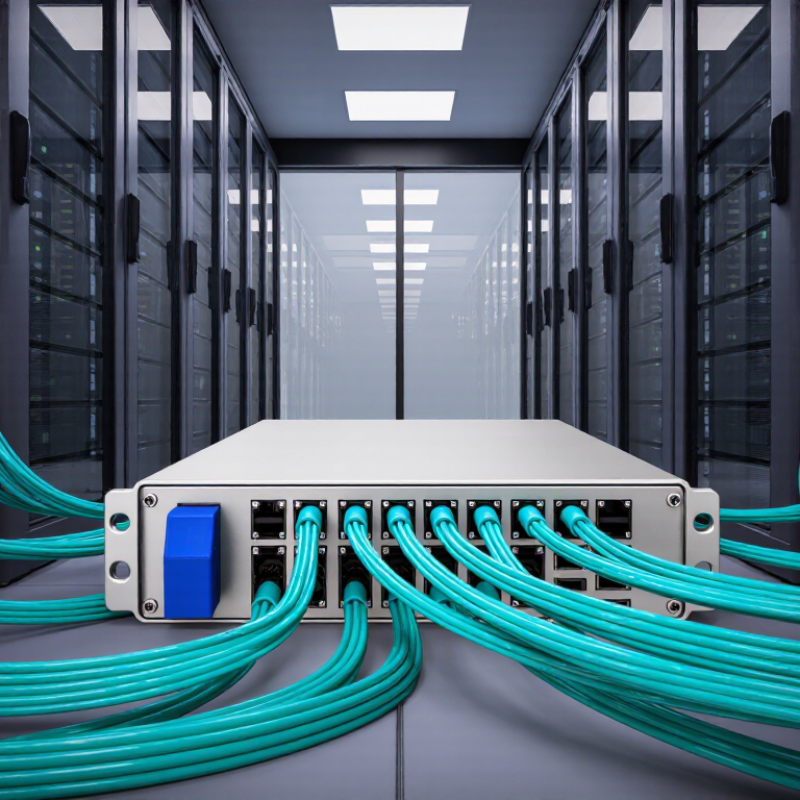
Why Choose a Multimode Transceiver for Global Networks?

Multimode Transceivers in IEEE 802.3: From 10 Gb/s to 400 Gb/s

Why Choose a Multimode Transceiver for Global Networks?

A multimode transceiver suits dense, short-reach links inside data centers and regional network facilities. It sends light through multiple paths in a wider optical core. This supports practical connections between switches, servers, and storage systems. Global networks are not one optical distance. Long-haul routes may need single-mode optics, while local sites often benefit from multimode simplicity and lower cabling costs. I have seen network plans fail when every link is treated as long-haul. The limitation is important.

Multimode transceivers in IEEE 802.3 have progressed from 10 Gb/s to 400 Gb/s. At 10 Gb/s, 10GBASE-SR commonly supports short links over OM3 or OM4 fiber. Higher rates use parallel optical lanes. 40GBASE-SR4 and 100GBASE-SR4 divide traffic across four lanes. 200 Gb/s and 400 Gb/s interfaces use more advanced lane arrangements, including SR4 and SR8 designs. These standards define transmission requirements, reach limits, and optical characteristics. They do not remove the need for careful fiber selection. Connector cleanliness still matters.

Tips: Check the installed fiber grade before ordering optics. Confirm lane count, connector type, and maximum channel length. Test the link after installation, not only during troubleshooting. A small loss budget error can become a serious outage. I would also leave capacity for future upgrades, even when the current design looks sufficient. That decision is easy to question later.

Why Choose a Multimode Transceiver for Global Networks?

Multimode transceivers support high bandwidth over short- and medium-distance links while enabling efficient upgrades from 10 Gb/s to 400 Gb/s.

The chart compares maximum specified link distances over OM3 and OM4 multimode fiber for representative IEEE 802.3 Ethernet interfaces. As data rates increase, parallel optical lanes and improved multimode cabling allow higher capacity within practical data-center and campus distances.

Reference standards: IEEE 802.3ae, IEEE 802.3ba, IEEE 802.3bm, and IEEE 802.3bs. Distances are maximum nominal link lengths in meters.

OM3–OM5 Reach Limits: 100G Extends 70–100 m (IEEE 802.3)

Why Choose a Multimode Transceiver for Global Networks?

Multimode transceivers suit short, high-density links in data centers and regional facilities. Their lower optical cost can simplify 100G deployments across server rows, equipment rooms, and campus buildings. For 100G links, reach depends strongly on the fiber grade. Under IEEE 802.3 specifications, OM3 typically supports up to 70 meters, while OM4 and OM5 can support up to 100 meters.

The usual figures are 70 meters on OM3 and 100 meters on OM4 or OM5. These distances assume compliant cabling, correct polarity, clean connectors, and verified insertion loss. Real rooms are less forgiving. A crowded patch panel, a tight bend, or repeated reconnections can reduce the available margin. During installation, technicians should inspect end faces, record test results, and confirm the transceiver and fiber combination before commissioning.

OM5 does not automatically provide a longer 100G reach than OM4. Its design can support broader wavelength applications, but the selected 100G optical standard still controls the practical distance. This detail is often missed in early planning. Multimode is not intended for intercontinental spans, yet it can serve global network architectures through many connected local sites. A careful design should map every link length, connector pair, and upgrade path. Sometimes, choosing multimode saves money. Sometimes, it creates a limit that appears later.

VCSEL Economics: 850 nm Multimode Optics for Short Data-Center Links

Why choose a multimode transceiver for global networks? For short data-center links, the answer often begins with practical economics. An 850 nm VCSEL transmitter uses mature components and supports efficient multimode fiber connections. This combination can reduce optical costs without weakening performance inside a controlled facility.

A technician may install a 100-meter link between a server row and a nearby aggregation switch. With OM3 or OM4 fiber, an 850 nm multimode transceiver can deliver high bandwidth across this distance.

Shorter links also reduce concerns about dispersion and optical loss. Power consumption is usually modest, which matters when thousands of ports operate continuously.

The installation is straightforward.

In real deployments, teams value simpler testing. A visual inspection, fiber cleaning, and loss measurement can reveal many faults before service begins. Multimode optics also offer a practical path for upgrading switch capacity while reusing existing cabling. That can reduce labor, rack changes, and disposal costs.

However, multimode is not perfect. It is generally less suitable for long campus or intercity spans, where single-mode optics provide better reach. Connector quality, bend radius, and fiber condition still affect reliability. I have seen inexpensive link plans become expensive after poor cable management caused repeated errors. The better decision comes from measuring distance, bandwidth, port density, and future expansion together, rather than choosing optics by headline speed alone.

Interoperability via MSA: SFP, QSFP, and QSFP-DD Form Factors

Why Choose a Multimode Transceiver for Global Networks?

Global networks need flexible links, not only higher speeds. Multimode transceivers support short and medium-distance connections across campuses, data halls, and regional facilities. Their value grows when equipment follows Multi-Source Agreement (MSA) dimensions and electrical expectations. SFP, QSFP, and QSFP-DD form factors let network planners match port density with capacity. SFP often serves lower-speed links, while QSFP supports higher bandwidth and breakout designs. QSFP-DD adds more lanes for dense, scalable deployments.

MSA improves mechanical interoperability, but it does not guarantee every optic will communicate perfectly. I have seen installations fail because teams checked the cage size but ignored wavelength, fiber grade, FEC, or software support. Small details matter. A multimode link also has distance limits. OM3, OM4, and OM5 fiber can produce different results at the same speed. Connector cleanliness matters too. Dust can turn a carefully planned link into an unstable one.

Tips: Confirm the host port’s supported MSA profile before ordering transceivers. Check lane mapping for QSFP and QSFP-DD breakout cables. Record fiber type, link distance, speed, and FEC settings. Test both ends under real traffic, not only with a basic light meter. Keep a few spare units from the same specification. Compatibility tables help, but field testing is still necessary. Mistakes happen. Careful documentation makes them easier to find.

400G Migration: Eight 50G PAM4 Lanes in 400GBASE-SR8 (IEEE 802.3bs)

Why Choose a Multimode Transceiver for Global Networks?

Global networks are moving closer to the 400G adoption curve. Synergy Research Group reported more than 1,000 hyperscale data centers worldwide in 2024. That growth increases pressure on short-reach, high-density connections. 400GBASE-SR8 addresses this need through eight 50G PAM4 lanes.

Defined by IEEE 802.3bs, 400GBASE-SR8 uses parallel multimode fiber lanes at 850 nanometers. It can support up to 70 meters over OM3 and 100 meters over OM4 fiber. Each lane carries 50 gigabaud PAM4 signaling. The architecture improves port density without forcing every link toward expensive single-mode infrastructure. Small details matter here. Clean connectors matter.

LightCounting’s 2024 optical market analysis identified artificial intelligence clusters and data-center expansion as major drivers for 400G and 800G transceiver demand. For operators, SR8 can simplify migration inside server halls, especially between switches and high-density compute cabinets. Multimode transceivers also allow familiar fiber practices and shorter patching routes.

The design is not perfect. Eight optical lanes create more points for insertion loss, polarity errors, and lane imbalance. Technicians should test every lane, not only the aggregate link. Existing cabling may also limit reach. A careful migration plan should verify OM3 or OM4 performance, connector cleanliness, and thermal clearance before deployment. Some networks will need more than a faster optic.

Why Choose a Multimode Transceiver for Global Networks? - 400G Migration: Eight 50G PAM4 Lanes in 400GBASE-SR8 (IEEE 802.3bs)
Data Dimension 400GBASE-SR8 Specification or Deployment Fact Migration and Network Planning Value
IEEE Ethernet Interface Defined in IEEE 802.3bs as a 400 Gb/s multimode-fiber Ethernet physical-layer interface. Provides a standards-based path for upgrading compatible data-center switching platforms to 400 Gb/s.
Optical Lane Architecture Eight optical lanes, each carrying 50 Gb/s using PAM4 signaling, combine to deliver 400 Gb/s. Parallel-lane architecture supports high aggregate bandwidth while using established short-reach multimode-fiber technology.
Typical Optical Wavelength Approximately 850 nm, generally implemented with short-wavelength VCSEL-based optics. 850 nm multimode optics are well suited to short, high-density interconnects inside data centers and network rooms.
Supported Fiber Type Laser-optimized multimode fiber, including OM3, OM4, and OM5 grades when the link design meets the applicable reach limits. Existing structured multimode cabling may be reusable, reducing the need for immediate replacement with single-mode infrastructure.
Reach on OM3 Fiber Up to approximately 70 m for a compliant 400GBASE-SR8 link. Suitable for short interconnects between racks, rows, and nearby network areas.
Reach on OM4 or OM5 Fiber Up to approximately 100 m under commonly specified 400GBASE-SR8 deployment conditions. Actual reach depends on channel loss, connectors, and installation quality. Provides practical coverage for many modern data-hall layouts while retaining a compact multimode design.
Fiber Polarity and Count Uses eight fibers for transmit and eight fibers for receive, requiring 16 optical fibers in total for a duplex parallel-fiber link. Fiber polarity and end-to-end lane mapping must be verified before installation to prevent lane reversal or link failure.
Common Connector Format Typically implemented with a 16-fiber push-pull multifiber connector, commonly arranged as eight transmit and eight receive positions. High-density multifiber connectivity helps conserve rack space, but connector cleanliness and polarity management are essential.
Modulation Format Four-level pulse-amplitude modulation (PAM4), which carries two bits per symbol and requires suitable signal-processing and error-correction techniques. Enables higher lane rates than traditional two-level signaling without doubling the number of parallel fibers.
Host-Side Data Rate Nominal aggregate Ethernet rate is 400 Gb/s; the physical implementation uses multiple high-speed electrical and optical lanes. Supports migration from lower-speed server, storage, and spine interfaces while maintaining a scalable switching architecture.
Power and Thermal Planning Power consumption varies by module design, coding, connector configuration, and operating temperature; it must be checked against the equipment specification. Thermal density should be evaluated during 400G upgrades because higher port density can affect rack airflow and cooling capacity.
Latency Consideration Multimode-fiber propagation distance is short, and the transceiver adds a small device-level processing delay; the total value depends on the complete equipment path. Well suited to latency-sensitive east-west traffic within data centers, although the transceiver should not be selected solely by nominal fiber distance.
Interoperability Boundary 400GBASE-SR8 is intended for compatible 400GBASE-SR8 endpoints and matching parallel multimode-fiber channel components. It should not be assumed to interoperate directly with 400G single-mode variants or other 400G multimode lane arrangements without an appropriate breakout or conversion design.
Breakout Migration Option A 400G port may be architected for breakout into lower-speed connections when the switch, transceiver, cabling, and software support the selected mode. Allows gradual migration from 100G-class access or aggregation links while preserving a higher-capacity spine port.
Best-Fit Network Segment Short-reach connections within data centers, high-performance computing environments, server rooms, and campus facilities with suitable multimode cabling. Offers a cost- and space-efficient option for local high-bandwidth links, but it is not intended to replace long-haul or metro single-mode solutions.
Key Installation Checks Verify fiber grade, insertion loss, polarity, lane mapping, connector cleanliness, bend radius, patch-panel compatibility, and total channel length. Detailed channel validation reduces PAM4-related margin problems and improves link stability during large-scale 400G deployment.
Primary Advantages 400 Gb/s aggregate capacity, eight 50G PAM4 lanes, high port density, short-reach multimode compatibility, and potential reuse of existing cabling. Provides a practical high-speed migration route for data-center networks where link distances remain within multimode-fiber limits.
Important Limitation The reach figures are channel-design targets rather than guarantees for every installation. Loss, connector quality, temperature, and fiber condition can reduce available margin. For links beyond multimode reach, use a standards-appropriate single-mode architecture instead of extending 400GBASE-SR8 beyond its intended application.

FAQS

What is a multimode transceiver best suited for?

It suits short links inside data centers and regional facilities. Typical connections include switches, servers, and storage systems. Not every network link needs long-haul optics.

What speeds can multimode transceivers support?

Multimode designs have progressed from 10G to 400G. Higher speeds use several parallel optical lanes. The exact lane arrangement depends on the interface design.

How far can a 400G multimode link reach?

A 400G eight-lane design can reach about 70 meters over OM3 fiber. It can reach about 100 meters over OM4 fiber. Actual performance depends on channel loss and installation quality.

Why are 850 nanometer optics common in data centers?

They use mature components for short multimode connections. This can reduce optical costs and power use. Thousands of active ports make small savings meaningful.

Can existing OM3 or OM4 cabling support future upgrades?

It may support higher speeds if distance and loss remain within limits. Check fiber grade, lane count, connectors, and channel length before ordering. Reuse sounds easy. Sometimes it is not.

What installation details affect multimode link reliability?

Clean connectors, correct polarity, and controlled bend radius are essential. Technicians should measure loss after installation. A dirty connector can interrupt an otherwise suitable link.

Should every lane be tested on a high-speed multimode connection?

Yes. Test each lane, not only the combined link result. Lane imbalance, insertion loss, or polarity errors can hide inside aggregate measurements. Small faults grow quickly.

When should a network use single-mode optics instead?

Single-mode optics are usually better for long campus or intercity spans. Multimode works best when distances stay short and predictable. Choosing only by headline speed can create expensive redesigns.

What should a 400G migration plan include?

Confirm OM3 or OM4 performance, connector cleanliness, polarity, and thermal clearance. Reserve capacity for future upgrades and higher port density. I might overestimate reuse if the old cabling was poorly managed.

Conclusion

A multimode transceiver is a practical choice for short-reach connections in modern data centers and global network infrastructure. IEEE 802.3 standards have expanded multimode optical technologies from 10 Gb/s to 400 Gb/s, while OM3, OM4, and OM5 fiber provide cost-effective performance for different reach requirements. For 100G links, multimode solutions can typically support distances of approximately 70 to 100 meters, depending on the fiber grade and implementation. Using 850 nm VCSEL technology also helps reduce optical costs and power consumption for high-density deployments.

Interoperability is supported through widely adopted MSA specifications and flexible form factors, including SFP, QSFP, and QSFP-DD. As networks migrate toward 400G, 400GBASE-SR8 uses eight 50G PAM4 lanes to deliver high bandwidth over parallel multimode fiber. This combination of standardized interfaces, scalable lane architecture, economical optics, and suitable short-distance reach makes multimode transceivers an effective option for data-center upgrades and high-speed network expansion.

Liam

Liam

Liam is a dedicated marketing professional with a profound expertise in the industry, where he excels at highlighting the unique advantages of our core products. With a keen understanding of market trends and consumer needs, Liam frequently updates our company’s professional blog, providing......