Fibronexa Fibronexa

What Are the Top LC Connector Transceiver Types?

Time:2026-10-10 Author:Mason
0%

Choosing the right LC connector transceiver can determine whether a fiber link runs smoothly or creates recurring maintenance problems. In data centers, I have seen small connector details affect installation time, signal stability, and future upgrades. An LC interface is compact, reliable, and widely used with duplex and single-fiber designs. Yet, not every transceiver with an LC port serves the same network purpose.

This guide examines the main LC connector transceiver types used in modern fiber systems. It will compare duplex modules for separate transmit and receive paths with BiDi modules that use one fiber for both directions. It will also consider multimode SR transceivers, single-mode LR and ER options, and wavelength-specific CWDM or DWDM modules. Each type has practical limits. Reach, fiber category, wavelength, data rate, and optical budget must match the complete link.

Details matter.

For example, an SR module may perform well across a short multimode connection but fail when paired with unsuitable single-mode fiber. A BiDi pair also requires matching transmit and receive wavelengths. This is easy to overlook during hurried upgrades. Compatibility lists from reputable manufacturers remain essential, especially when replacing older equipment. Still, vendor labels can simplify complex conditions too much. Real deployment results depend on connector cleanliness, patch-panel quality, bend radius, and switch configuration. By examining these factors together, readers can make a more reliable choice instead of selecting an LC connector transceiver by appearance or price alone.
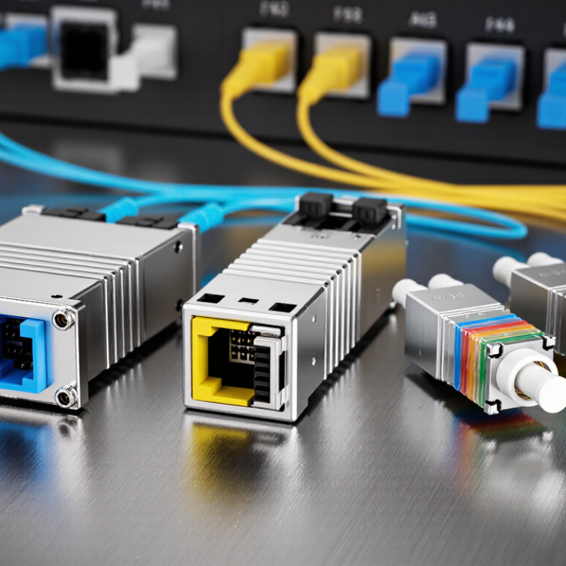
What Are the Top LC Connector Transceiver Types?

LC Connector Transceiver Fundamentals and Key Design Features

LC connector transceivers use a compact, latch-based interface for dense fiber connections. Their small form factor suits switches, servers, patch panels, and high-density transport equipment. The LC interface normally uses 1.25 mm ferrules and supports simplex or duplex operation. Duplex models transmit and receive through two fibers. Simplex models use one fiber, while bidirectional designs send signals in opposite directions over a single strand.

The main types include single-mode and multimode transceivers. Single-mode versions commonly support longer distances through narrow optical cores and carefully controlled wavelengths. Multimode versions target shorter links inside buildings or equipment rooms. Data rates may range from basic Ethernet speeds to high-speed network standards. Reach, wavelength, fiber type, and connector polish must match the installed link. A mismatch can produce weak signals, packet errors, or unstable performance.

Design quality depends on more than speed. Engineers should examine insertion loss, return loss, operating temperature, power consumption, and electromagnetic shielding. Digital diagnostics can report temperature, voltage, bias current, and optical power during operation. This helps technicians identify a dirty connector or failing fiber before service interruption occurs. The locking tab should resist accidental removal, yet remain easy to release during maintenance. Polarity also matters, especially in duplex assemblies.

Small details matter.

In field testing, specifications sometimes look better than real results. Dust, tight bends, and poor cleaning can reduce the expected reach. A reliable installation therefore includes inspection, cleaning, and optical power testing. No design is perfect, and thermal performance deserves another review when transceivers operate in crowded cages.

Single-Mode LC Transceiver Types for Long-Distance Links

LC connectors remain common in single-mode transceivers for long-distance links because their duplex design supports separate transmit and receive paths. Typical options include 1G LX for links up to 10 km, 10G LR for 10 km, and 25G LR for similar distances. These figures follow IEEE 802.3 specifications. For longer spans, 10G ER can reach about 40 km under suitable conditions. Some 100G LR4 and ER4 modules also use duplex LC interfaces, while many higher-density designs use multifiber connectors instead.

The connector is only one selection factor. Engineers must match wavelength, fiber type, reach, optical budget, and switch compatibility. A 1310 nm module usually fits standard single-mode fiber better than a short-reach multimode design. LightCounting’s 2024 Optical Transceiver Market Report projects the optical transceiver market to exceed 20 billion US dollars by 2028. That growth reflects rising data-center and telecom demand, but the forecast does not remove installation risks. A dusty LC end face can increase loss quickly. I have seen “10 km” links fail because patch-panel cleaning was treated as optional.

Tips: Check the IEEE class, not only the product label. Measure insertion loss with an optical power meter. Keep LC polarity consistent. Leave margin for aging, splices, and temperature changes. If a link barely passes today, it may become unstable later.

Multimode LC Transceiver Types for Shorter Network Connections

What Are the Top LC Connector Transceiver Types?

Multimode LC Transceiver Types for Shorter Network Connections

Multimode LC transceivers suit short network connections in data centers, campus rooms, and server cabinets. They commonly use an 850 nm optical source with OM3 or OM4 multimode fiber. The LC connector is compact and usually carries two fibers for duplex communication. This design saves rack space and supports tidy patch-panel layouts.

For lower data rates, SFP transceivers can support short multimode links in access networks. SFP+ models are widely used for 10 Gigabit Ethernet connections. SFP28 versions can serve 25 Gigabit links when the switch, fiber, and transceiver share compatible specifications.

QSFP+ and QSFP28 options provide higher port density, although their front connectors may use parallel fiber interfaces instead of a simple duplex LC connection.

Check the details carefully.

Link distance depends on fiber grade, transceiver power, connector quality, and installation conditions. A 10G module may reach much farther over OM4 than OM1, for example. Dust on an LC end face can increase loss and cause unstable links. I have seen short connections fail because technicians measured cable length but ignored bend radius. That assumption is easy to make, yet it is incomplete. Always verify wavelength, speed, fiber type, polarity, and optical budget before deployment. Compatibility tables help, but they should not replace equipment documentation or actual test measurements.

BiDi, CWDM, and DWDM LC Transceiver Variations

What Are the Top LC Connector Transceiver Types?

LC transceivers commonly support BiDi, CWDM, and DWDM designs. Each option solves a different fiber capacity problem. BiDi modules transmit and receive on one fiber. They use separate wavelengths in opposite directions. A matched wavelength pair is essential. Installers often choose BiDi when spare fiber is limited, especially in compact access networks. One fiber helps, but compatibility becomes less forgiving.

CWDM transceivers place several widely spaced wavelengths on the same fiber. This approach expands capacity without demanding extremely narrow channel control. It suits metro links, campus networks, and moderate-distance connections. DWDM uses tighter wavelength spacing and supports many more channels. It can serve high-capacity, longer-distance systems, but requires careful planning. Optical power, dispersion, channel spacing, and noise margins all matter. More capacity brings more engineering work. That trade-off is easy to underestimate.

Tips: Check the fiber type, transmission distance, wavelength, and connector polish before ordering. Confirm the BiDi upstream and downstream pair. For CWDM, verify the channel plan and multiplexer compatibility. For DWDM, review loss budgets and optical signal quality. Clean LC connectors with approved tools; tiny particles can cause serious attenuation. Digital diagnostics can reveal temperature or power changes, but readings are not always perfect. Field checks should support, not replace, measured link testing.

How to Select the Right LC Transceiver for a Network Application

What Are the Top LC Connector Transceiver Types?

Selecting the right LC transceiver starts with the network’s actual operating conditions. Duplex LC modules use two fibers for separate transmit and receive paths. BiDi modules use one fiber and require matched upstream and downstream wavelengths. This saves cable space, but wavelength pairing must be checked carefully.

Multimode transceivers suit short links inside data centers and equipment rooms. They commonly support 850 nm transmission over OM3 or OM4 fiber. Single-mode modules serve longer campus, metro, and service-provider links. Their reach may range from a few kilometers to many more, depending on the optical design. Do not choose by distance alone. Fiber type, connector cleanliness, insertion loss, and patch-panel quality also affect stability.

Speed and host compatibility matter just as much. An SFP module may support 1 Gb/s, while SFP+ and SFP28 modules support higher rates. The switch must recognize the selected data rate and optical specification. Check the port standard, supported wavelengths, transmission distance, operating temperature, and digital monitoring functions. DOM readings can reveal rising temperature or weakening optical power before a failure occurs.

A field installation taught me a useful lesson. The calculated link budget looked safe, yet dirty LC ends caused intermittent errors. Cleanliness is not a minor detail. It deserves inspection records. I also once selected a longer-reach module for a short link, assuming extra capacity was harmless. That choice increased cost and sometimes reduced flexibility. The better decision matches the transceiver to the fiber plant, traffic demand, maintenance plan, and future expansion.

FAQS

What is an LC connector transceiver?

It is a compact optical module using a latch-based LC interface. It supports dense connections in switches, servers, and patch panels. Small details matter.

What is the difference between duplex and simplex LC transceivers?

Duplex models use two fibers for separate transmission and reception. Simplex models use one fiber for one-way communication. Bidirectional models send opposite signals through one fiber.

Should I choose single-mode or multimode?

Choose single-mode for longer campus, metro, or service-provider links. Choose multimode for shorter connections inside buildings or equipment rooms. The fiber plant decides.

Which specifications must match the installed fiber link?

Match fiber type, wavelength, reach, optical budget, and connector polish. Also verify port speed and host equipment compatibility. A mismatch can cause packet errors or unstable service.

How far can single-mode LC transceivers transmit?

Common 1G and 10G long-reach options may support about 10 kilometers. Some extended-reach designs may support approximately 40 kilometers. Actual distance depends on loss, splices, bends, and temperature.

What should I check before installing a long-distance LC transceiver?

Check the optical class, wavelength, fiber type, and link budget. Inspect and clean every LC end face before connection. Then measure insertion loss with an optical power meter.

Why are digital diagnostics useful?

Diagnostics can show temperature, voltage, bias current, and optical power. These readings may reveal a dirty connector or weakening fiber early. Not always.

Can a longer-reach transceiver improve a short link?

Not necessarily. It may increase cost and reduce configuration flexibility. A suitable module should match current traffic, fiber conditions, and future expansion. More capacity is not automatically better.

How can duplex LC polarity affect network performance?

Duplex polarity must keep transmission connected to reception at both ends. Incorrect polarity can prevent the optical link from operating. Check the pair before closing the patch panel.

What installation problems commonly reduce expected reach?

Dust, tight bends, poor cleaning, splices, and crowded equipment cages can increase loss. A link rated for 10 kilometers may fail under poor field conditions. My earlier assumption was too optimistic.

Conclusion

An LC connector transceiver is a compact fiber-optic module designed to transmit and receive data through LC connectors, offering secure connections, efficient space usage, and reliable network performance. Its selection depends on factors such as transmission distance, fiber type, data rate, wavelength, and network architecture. Single-mode LC transceiver types are well suited for long-distance links because they support low-loss transmission across extended fiber routes, while multimode versions are commonly used for shorter connections within buildings, data centers, and local network environments.

Different network requirements may call for specialized LC transceiver variations. BiDi models use separate wavelengths over a single fiber, helping reduce cabling needs. CWDM and DWDM models support multiple optical channels, increasing fiber capacity for growing networks. To choose the right solution, network designers should evaluate link distance, available fiber infrastructure, required bandwidth, wavelength compatibility, power budget, and future expansion plans. A careful match between the transceiver and application improves stability, scalability, and overall network efficiency.

Mason

Mason

Mason is a seasoned marketing professional with a deep expertise in the company's offerings and a passion for driving brand awareness. With a strong background in digital marketing strategies, he has an innate ability to connect with diverse audiences and effectively communicate product benefits.......