Fibronexa
Choosing the right CWDM transceiver is rarely a matter of selecting the highest data rate. It is a careful match between wavelength, fiber distance, optical power, connector type, and network design. A module that looks excellent on paper may still fail across a long outdoor link, especially when connectors are dirty or temperatures change. Small details matter.
Charles K. Kao, widely known as the “father of fiber optics,” said, “The future of communications is optical.” His vision explains why optical components deserve disciplined evaluation, not casual comparison. In practical CWDM deployments, engineers must check insertion loss, receiver sensitivity, wavelength spacing, DOM support, and compatibility with switches or multiplexers. The transceiver must fit the complete optical path.
Specifications can mislead. Sometimes.
This guide presents ten practical tips for choosing a reliable CWDM transceiver. It considers single-mode fiber, link budgets, operating temperature, vendor documentation, warranty terms, and testing evidence. It also questions a common assumption: longer reach is not automatically better. Excess optical power can create problems, while an underestimated loss budget can cause unstable links. The right choice depends on measured conditions, not marketing language alone. A cautious decision may require reviewing port coding, confirming interoperability, and testing one sample before deployment. Even experienced teams can overlook a minor wavelength mismatch. That is why every selection should be checked against the actual network diagram, optical budget, and maintenance environment.
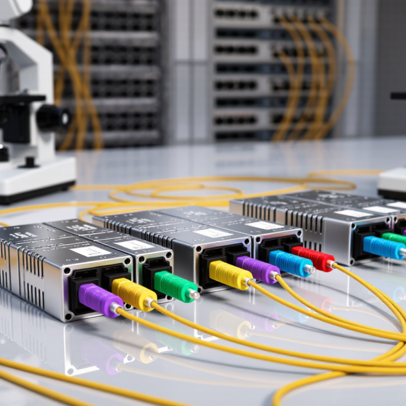
Define the network objective before choosing a CWDM transceiver. The International Telecommunication Union reported 5.4 billion internet users in 2023, equal to 67% of the global population. This growth keeps increasing pressure on metro and access networks. Decide whether your priority is added capacity, longer reach, lower latency, or simpler maintenance. A vague objective often creates an expensive mismatch.
Tip 1
Record the required data rate, fiber distance, connector type, and operating temperature. Check the optical power budget, not only the advertised reach. CWDM commonly uses 20 nm channel spacing under ITU-T G.694.2, with wavelengths from 1271 to 1611 nm. However, real links may lose performance through aging, splices, dirty connectors, or unexpected bends. I have seen short links fail because engineers trusted distance figures too much.
Tip 2
Match the transceiver to your network’s next three years, not only today’s traffic. Reserve suitable wavelengths for expansion, and confirm compatibility with multiplexers, demultiplexers, and monitoring systems. The International Telecommunication Union’s 2023 data also shows that billions remain offline, suggesting continued connectivity growth. Still, forecasting is imperfect. Leave practical headroom, but avoid paying for unused channels, excessive reach, or unnecessary management features. Check interoperability carefully before deployment.
Choosing the right CWDM transceiver starts with wavelength discipline. Check the channel plan before ordering. A 1310 nm module cannot replace a 1550 nm module without matching equipment. Confirm both ends use the same wavelength. Keep channel spacing records. Small labeling mistakes can disrupt an entire link. They happen more often than expected.
Match the transceiver to the fiber already installed. Single-mode fiber suits long CWDM connections. Multimode fiber usually needs different optics and shorter reach. Never rely on connector shape alone. Inspect the fiber type, core size, and attenuation budget. Then compare the module’s operating distance with the actual route. Include patch panels, splices, and bends. A “20 km” rating may become unrealistic after several losses. Leave engineering margin.
Check transmitter power and receiver sensitivity together. Their difference should exceed total link loss. Verify the connector polish and duplex orientation. Confirm the operating temperature for the equipment room or outdoor cabinet. Review DOM readings when available. They can reveal rising temperature or weak optical power early. Test the spare unit before deployment. I once trusted a clean label and missed a wavelength mismatch. It was an avoidable delay. Also confirm network speed, duplex mode, and system compatibility. A transceiver can fit physically and still fail operationally. Record every choice in the link documentation. Clear records make future replacements faster and safer.
| Tip | Selection Dimension | What to Check | Typical Data or Example | Practical Recommendation |
|---|---|---|---|---|
| 1 | Wavelength Compatibility | Confirm that the transceiver wavelength matches the passive CWDM multiplexer, demultiplexer, or optical add-drop filter port. | Common CWDM channel centers use a 20 nm spacing, such as 1270 nm, 1290 nm, 1310 nm, 1330 nm, 1350 nm, 1370 nm, 1390 nm, 1410 nm, 1430 nm, 1450 nm, 1470 nm, 1490 nm, 1510 nm, 1530 nm, 1550 nm, and 1570 nm. | Use the exact channel plan specified by the optical line system. Do not select a wavelength based only on the connector type or data rate. |
| 2 | Fiber Type | Verify that the module is designed for single-mode fiber and check the installed fiber specification. | Most CWDM transceivers are intended for 9/125 µm single-mode fiber, commonly classified as OS2 for outdoor and long-distance cabling. | Do not use a CWDM optic designed for single-mode transmission over multimode fiber unless the equipment documentation explicitly supports it. |
| 3 | Transmission Distance | Compare the rated reach with the actual fiber length, patch-panel connections, splices, and passive component losses. | Typical CWDM transceiver reaches include 10 km, 20 km, 40 km, and 80 km. The actual distance depends on wavelength, optical power, receiver sensitivity, and link loss. | Select a reach rating that exceeds the calculated link distance, but avoid relying on distance labels without checking the optical power budget. |
| 4 | Data Rate and Interface | Match the optical module to the host port speed, form factor, and electrical interface. | Common applications include 1.25 Gb/s Ethernet, 2.5 Gb/s SONET/SDH, 4.25 Gb/s Fibre Channel, and 10 Gb/s Ethernet. Form factors may include SFP, SFP+, or other equipment-specific designs. | Check the switch or router documentation for supported module types, coding requirements, and nominal line rate. |
| 5 | Optical Power Budget | Calculate whether the transmitter output power minus the receiver sensitivity is sufficient for the complete link. | A basic link budget is: transmitter output power − receiver sensitivity. For example, a 5 dB budget may be insufficient after fiber, connector, splice, and multiplexer losses are included. | Allow an engineering margin, commonly around 2–3 dB, for aging, temperature changes, repairs, and measurement uncertainty. |
| 6 | Fiber Attenuation | Use the attenuation value of the installed fiber at the selected wavelength rather than assuming one value applies to all channels. | Modern single-mode fiber may have attenuation around 0.35 dB/km at 1310 nm and approximately 0.22–0.25 dB/km near 1550 nm, subject to the cable specification. | For longer links, calculate attenuation separately for each wavelength and include the loss of every passive component. |
| 7 | Connector and Polarity | Check connector type, duplex polarity, transmit/receive orientation, and the required patch-cord configuration. | LC duplex connectors are widely used with pluggable transceivers. A duplex link requires the local transmitter to connect to the remote receiver. | Clean and inspect every connector before installation. Incorrect polarity or contaminated end faces can cause high loss or link failure. |
| 8 | Chromatic Dispersion | Evaluate dispersion for high-speed or long-distance links, especially when using wavelengths near the longer-wavelength portion of the CWDM range. | At 10 Gb/s and above, chromatic dispersion can become a major limitation. The acceptable dispersion depends on the transceiver design and its specified dispersion tolerance. | For long 10 Gb/s links, verify the maximum dispersion specification and consider dispersion-tolerant optics or an alternative optical design when required. |
| 9 | Operating Environment | Match the module temperature grade and environmental specifications to the installation location. | Typical temperature categories include commercial operation around 0°C to 70°C and extended operation around −40°C to 85°C, depending on the module and host equipment. | Use an extended-temperature transceiver for outdoor cabinets, industrial sites, unconditioned rooms, or locations with substantial seasonal temperature changes. |
| 10 | Monitoring and Interoperability | Check digital optical monitoring, management support, coding, and interoperability with the host device. | Digital monitoring may report temperature, supply voltage, laser bias current, transmit power, and receive power. Supported monitoring functions vary by module and host platform. | Confirm that the host can read the module correctly and that the reported optical values are suitable for troubleshooting and preventive maintenance. |
Choosing a CWDM transceiver starts with the equipment already installed, not the product label. Check switch or router port speed, duplex mode, coding, and supported optics. A 10G port may reject a module that matches the wavelength but uses unsupported signaling. Confirm the host port accepts the required MSA form factor and electrical interface. Small details matter.
Match the optical side to network standards. Verify the wavelength against ITU-T G.694.2 CWDM channel spacing and the planned passive multiplexer. Confirm single-mode fiber, connector polish, insertion loss, and maximum link distance. Measure the link budget, including splice and patch-panel losses. Leave engineering margin. It is easy to trust a nominal reach value too much. Temperature ratings must also match the cabinet, especially in unconditioned sites. Check whether the transceiver supports DOM, alarm reporting, and required FEC behavior. These features help maintenance only when the host system can read them.
Use the equipment supplier’s compatibility list as evidence, not the only decision. Compare the module datasheet with the router manual and network design. Test one unit under real traffic before ordering dozens. Watch for link flaps, excessive optical power, and rising error counts. A clean laboratory link can hide field problems. Record wavelength, measured power, and firmware behavior. I would recheck assumptions after installation; a spreadsheet can miss a connector or aging patch lead. Reliable selection depends on verified interoperability.
Compare wavelength, channel spacing, reach, and connector type before comparing prices. ITU-T G.694.2 defines CWDM channels on a 20 nm grid, commonly from 1271 to 1611 nm. Confirm the transceiver’s wavelength against the installed multiplexer. A near match is not enough. Check transmitter power, receiver sensitivity, and optical budget together. IEEE 802.3 identifies 10GBASE-LR operation up to 10 km over suitable single-mode fiber, but real routes include connectors, bends, and aging loss. Leave a practical margin of at least 3 dB. Measure twice.
Reliability depends on more than a datasheet temperature range. Review operating temperature, humidity limits, digital diagnostics, and alarm behavior. The Uptime Institute’s 2024 Global Data Center Survey reported that 16% of recorded outages cost between 100,000 and 1 million dollars. That figure makes monitoring more than a convenience. Check bias current, laser temperature, received power, and error counters during live testing. Select modules with traceable test records and consistent firmware support. IEC 60825-1 safety classification should also be verified before installation. Small details matter.
Field experience shows that compatibility failures often appear after thermal cycling, not during a short bench test. Test each channel at its intended wavelength, speed, and fiber length. Confirm interoperability with the actual switch and patch panels. Review insertion loss at both ends. I once treated a clean optical budget as proof of reliability; it was not. Operating conditions change, and neglected dust can defeat excellent specifications. Keep spare units stored within the manufacturer’s stated limits, then retest them before deployment.
Cost is more than the transceiver’s purchase price. Measure everything. Include multiplexers, fiber patching, installation labor, spare units, testing, and power consumption. A low-cost optic can become expensive after compatibility failures. Check optical budget, connector type, operating temperature, and digital monitoring before approval. Ask for written interoperability evidence, not verbal reassurance. Support matters. Require clear response times, firmware access, replacement procedures, and technical escalation. A practical service agreement should define remote troubleshooting and advance replacement terms. In field planning, I have seen delayed support extend a simple link repair into a weekend outage.
Scalability deserves equal attention. The 2023 ITU Facts and Figures report estimated 5.4 billion people used the Internet, representing 67% of the global population. That growth keeps pressure on access and aggregation networks. Choose optics that follow the ITU-T G.694.2 CWDM wavelength grid and match the existing channel plan. Reserve dark channels where possible. Confirm whether future upgrades require new multiplexers, different reach, or stricter dispersion limits. Ask vendors for a three-year roadmap, test records, product-change notices, and realistic end-of-sale commitments. Model growth at 30%, 60%, and 100% capacity. The middle case is often too optimistic. A spreadsheet can still lie. Verify assumptions with measured fiber loss, actual rack space, and documented vendor support.
Both ends must match the channel plan and wavelength. A 1310 nm module cannot replace a 1550 nm module without compatible equipment. Check labels carefully. Small mistakes can interrupt the entire link.
Single-mode fiber usually supports longer CWDM distances. Multimode fiber generally requires different optics and shorter reach. Inspect the core size, fiber type, and attenuation budget. Connector shape alone proves very little.
No. A rated distance may ignore real installation losses. Include patch panels, splices, connectors, and sharp bends. A “20 km” rating can become unsuitable after several losses. Leave engineering margin. That margin is easy to underestimate.
Compare transmitter power and receiver sensitivity together. Their available difference must exceed total link loss. Measure the route whenever possible. Do not rely only on product labels.
Confirm wavelength, fiber type, connector polish, and duplex orientation. Check network speed, duplex mode, and system compatibility. A module may fit physically but still fail operationally. Physical fit is not enough.
Confirm the equipment room or outdoor cabinet temperature range. Review digital optical monitoring readings when available. Rising temperature or weak optical power can reveal trouble early. Check the spare unit before deployment. I once trusted a clean label. It caused an avoidable delay.
Include optics, multiplexers, patching, installation, testing, spares, and power use. A cheap optic can become expensive after compatibility problems. Request written interoperability evidence before approval. Verbal reassurance is not enough.
Follow the existing wavelength plan and reserve unused channels when possible. Model demand at 30%, 60%, and 100% capacity. Check future multiplexer needs, reach limits, and dispersion constraints. Ask about product changes, testing, support, and replacement timelines. A spreadsheet can still lie. Verify assumptions with measured fiber loss and available rack space.
Choosing the right CWDM transceiver begins with clearly defining your network objectives, including required bandwidth, channel capacity, transmission distance, and future expansion plans. Confirm that the transceiver’s wavelengths match the CWDM system and that its fiber type, connector design, and reach are suitable for the existing infrastructure. It is also important to verify compatibility with switches, routers, multiplexers, and relevant network standards to avoid installation or interoperability issues.
Next, compare optical performance, including transmission power, receiver sensitivity, operating temperature, and monitoring capabilities. A reliable CWDM transceiver should provide stable operation under the environmental conditions of the deployment site and support efficient maintenance. Finally, evaluate the total cost rather than focusing only on the initial purchase price. Consider energy consumption, warranty coverage, technical support, replacement availability, and long-term scalability. A carefully selected solution can improve network reliability, simplify future upgrades, and deliver better value throughout its service life.